| Name | Last modified | Size | Description | |
|---|---|---|---|---|
| Parent Directory | - | |||
| README_html_9dd15e158e8417d2.png | 2022-11-23 22:25 | 9.5M | ||
| README_html_1033fa5b834b4f59.png | 2022-11-23 22:25 | 22K | ||
| README.html | 2023-11-18 17:32 | 12K | ||
| Temperature Sensors/ | 2020-10-02 21:11 | - | ||
| TI_Kits/ | 2022-11-23 22:31 | - | ||
| LIDAR/ | 2020-10-30 20:35 | - | ||
| LCD44780/ | 2020-10-02 21:54 | - | ||
| I2CXL-MaxSonar/ | 2021-12-05 20:20 | - | ||
This project aims to develop a small system using a TIVA TM4C123G. The main objective is collecting information from a serial interface connected to a small communication device. The system uses an I2C temp sensor for measuring the temperature of an object and a PWM-based driver for some actuator. Peripherals like a keyboard and an LCD are used as the means to interact with system.
In this directory one can find details about the hardware and software that might be used in the project or potentially can support its development. Hence, you should explore these folders in order to see if anything can be handy in your project.
To kickoff your developments an example of the use of the LCD peripheral with the TIVA TM4C123G Launchpad on the ENERGIA IDE is shown.
Enjoy
In this example the capabilities of LCD programming using the TM4C123G and the lCD libraries associated with the LCD managed by the LCD44780 controller.

Details of the functionality of the controller can be found here

Besides an LCD, a simple push button will be used to demonstrate the interaction with an input device.
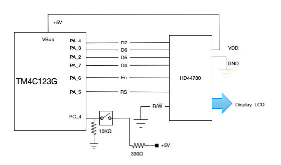
This section illustrates the connections of the components. The block diagram is shown in the following figure:


The LCD VDD has to be mandatorily connected to a 5V source. Due to the fact that we are using +5V in the power rail of the breadboard, a 330Ω resistor has to be connected to the push button to limit the current into the µC port which is internally powered @ 3.3V.

IMPORTANT NOTE: in the project, ONLY the LCD should be connected to the Vbus pin;
every other device works with 3.3V; Please connect the 3.3V and GND rails to the power bus

on the breadboard so that everything can be referenced to those levels (there is a real

 DANGER of destroying TIVA GPIO pins if a +5v level is used).

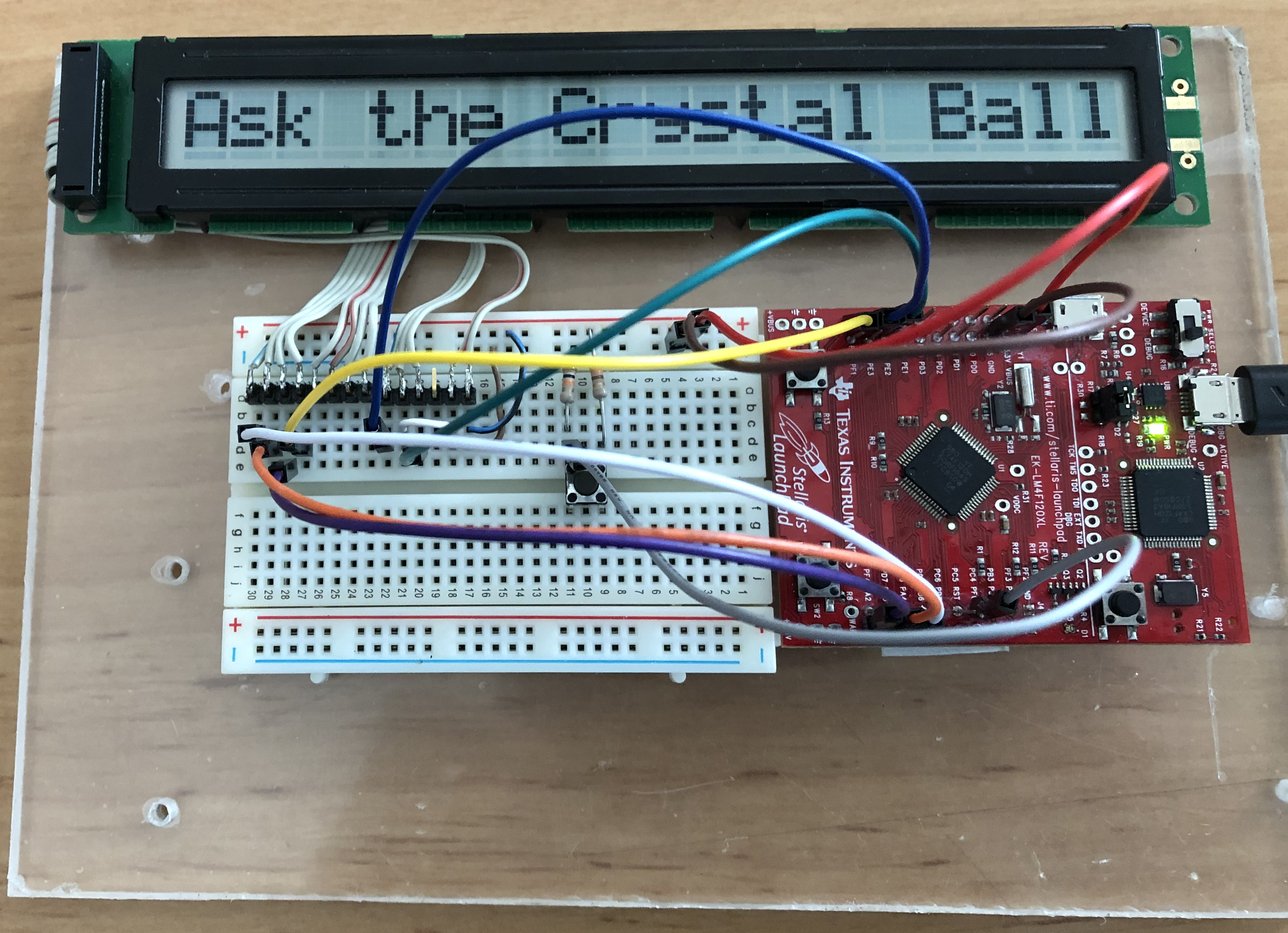
Images - here there is a picture of the global assembly with all elements

The crystal_ball code is listed below.
It uses 6 GPIOs from Port_A and one bit from Port_C for reading the push button. There is no debouncing due to the delays of the loop. Note, however, that in a normal keyboard there is bouncing and so a debouncing technique should be used.

/*  --- The CRYSTAL BALL --- */

// include the library code:
#include <LiquidCrystal.h>

// initialize the library by associating any needed LCD interface pin
// with the TM4C123G pin number it is connected to
const int rs = 8, en = 9, d4 = 10, d5 = 11, d6 = 12, d7 = 13;
//        PA_5    PA_6    PA_7    PA_2      PA_3     PA_4
LiquidCrystal lcd(rs, en, d4, d5, d6, d7);

const int switchPin = 37; //PC_4
int switchState = 0;
int prevSwitchState = 0;
int reply;

void setup() {
  // set up the LCD's number of columns and rows:
  lcd.begin(20, 1);
  pinMode(switchPin,INPUT);
  lcd.print("Ask the ");
  lcd.print("Crystal Ball!");
}

void loop() {
  switchState = digitalRead(switchPin);
  if (switchState != prevSwitchState) {
    if (switchState == LOW) {
      reply = random(8);
      lcd.clear();

    lcd.setCursor(0,0);
    lcd.print("The ball says:");
    delay(1000);
    lcd.autoscroll();
    lcd.setCursor(20,0);

    switch(reply){
      case 0:
        lcd.print("Yes           ");
        break;
      case 1:
        lcd.print("Likely        ");
        break;
      case 2:
        lcd.print("Certainly     ");
        break;
      case 3:
        lcd.print("Seems Good    ");
        break;
      case 4:
        lcd.print("Unsure        ");
        break;
      case 5:
        lcd.print("Ask again     ");
        break;
      case 6:
        lcd.print("Doubtful      ");
        break;
      case 7:
        lcd.print("No            ");
        break;
    }
    lcd.noAutoscroll();
    delay(1000);
    lcd.clear();
    lcd.print("Ask the Crystal Ball!");
  }
 }
 prevSwitchState = switchState;
}